Hi peeps,
I spend a lot of my time practicing at night with a Victory Kraken (50w) on low power mode and considering that its a bastard loud tube amp, it actually sounds pretty good. I wondered whether it would be worth investing in a reactive load of some sort and use an IR instead as I could do with cranking the amp a little more and I could play through headphones when the wife and kids are around.
So, my (noob) questions are;
1- is it worth it (tonally) to go down this route?
2- any suggestions on gear? (Small budget )
3- I don’t have a PC/mac/laptop to use, is it possible/worth it to do it without one?
4- should I just get a reactive attenuator like the fryette powerstation 2?
Do you want to use a tube amp with zero sound? If so, you can use a load box. Especially if you’re a high gain player where the differences can be mostly dialed out via EQ if you need to.
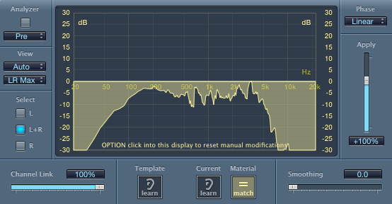
I’ve done extensive A/B tests with this a few years back, and older non-reactive loads like the Palmer Speaker Simulator really eff up your sound. Using something like Match EQ in Logic will show you exactly what’s being removed, and also allow you to dial back in the removed portion of the frequency spectrum for a tone which is nearly indistinguishable from the original, miked / amplified cabinet. Again, this works best for high gain playing where dynamics aren’t an issue because everything is squashed anyway. So in short, you can even use a cheap non-reactive box if all you’re looking for is a good distortion tone coming back from your speakers or headphones with zero cab volume.
I haven’t tested the newer generation of load boxes like the Two Notes Torpedo and the Universal Audio OX. But if we’re expecting them to sound identical to a particular amp / cab pairing, that’s going to be tough. It’s not just the fact that the amp is plugged into a speaker. It’s the specific model of speaker that’s plugged in which creates differences in the amp’s response. If you load down your amp with a generic reactive load box, even a good one, it’s not the same same as loading it down with a 4x12 filled with greenbacks, versus a 2x12 filled with Celestion V30s, and so on. Each of those cabinets will produce a different response from the amp.
That being said… unless you’re trying to exactly duplicate the sound of a particular amp through a particular cabinet, it probably doesn’t matter that much. A good reactive load box will probably still produce a sound that’s realistic and better than what the Palmer generation of devices produced. Andy Wood uses the OX and loves it, for example.
For a deeper dive on impulse responses and cabinets, here’s a post from a few years back:
No prob. I should also mention that we DI the amp with an IR on it for all our recordings — everything you hear from us. However, we do the DI with the speaker still plugged in. So it’s still loud in the room, and the amp is still respoding as it normally does.
When you A/B the miked track versus the IR track this way, they are identical. Tiny differences in mic position from day to day produce a much more drastic difference in tone coming back than the difference between the IR and the mic track done from the same mic position.
I know this isn’t relevant for your scenario because you’re looking for quiet, but just as an illustration of why the speaker being plugged in affects tone even when you’re not actually miking the speaker. There are some audio samples of this in the article above.
It makes sense that the having the speaker connected is an important part as the act of adding an attenuator interrupts the interaction between amp and load… its electrical voodoo and I don’t even pretend to understand it… thanks again for your post Troy!
The speaker load thing is nothing but frequency-dependent gain, which is another term for EQ. It’s easily replaceable with a tuned EQ circuit.
Even with the speaker connected, you’re missing the cabinet response, which is most of what the IR is putting back. The famed ‘speaker interaction effect’ is pretty small in comparison.
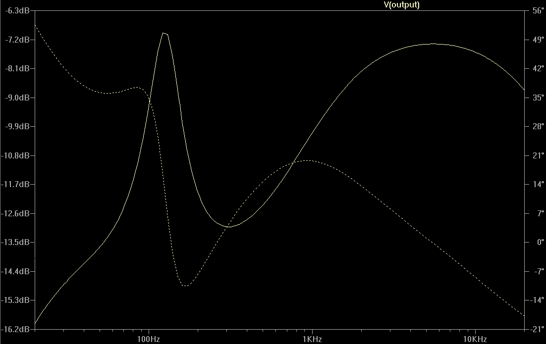
This may be what you’re already saying, but when I tested this the frequency rolloff from the non reactive load was huge. A giant dip with a wide Q at around 100hz. And a similarly large drop in the treble that efffectively low-passed the entire top end. I can dig up the Logic files with the gain-normalized tests of a popular attenuator model if anyone is interested.
You can definitely add it back with EQ but the trick is knowing what to add back. The compensation knobs on the Palmer don’t come anywhere close to adding back the correct curves, for example. If you’re not A/B-ing with the miked cab I don’t know how you would know what compensation curve to dial in for the speakers in question.
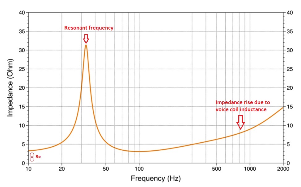
The general idea of the speaker impedance effect is that higher impedance in the speaker itself generates greater amplification, and the speaker has a frequency-dependent impedance curve.
This is the free resonance of the speaker mounted in the cabinet. If you shake the cabinet, this is the frequency the speaker wants to vibrate at. This motion generates current in the voice coil that opposes the motion of the magnet, which looks just like resistance to the transformer, and so generates a high-Q EQ bump at the resonant frequency, and gives a bit of extra thump.
This is due to the inductance of the voice coil. Inductors increase impedance with frequency.
Neither of these effects was intentionally designed into the amplifier, they are largely just unavoidable consequences of speaker design, but it turns out most of us like the way they sound. Engineers generally aim at fidelity rather than interesting coloration, and linear amplification was a mythical beast at the time guitar amplifiers were invented, so this was all entirely accidental.
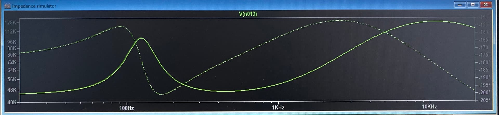
The impedance effect looks like a big deal in the plot, but that’s often misleading because of this plot:
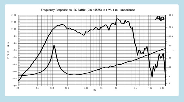
This a typical frequency response of a guitar speaker cabinet, on the same plot as a typical impedance curve. Take a look at the frequency axis and compare the interesting parts of the two curves. Notice that guitar speakers are not full-range transducers. They drop off pretty sharply below a few hundred Hz and above 5k. This means that much of the boost from the impedance effect is not reproduced anyway. Very often, the bulk of the resonance peak is off to the left of the corner frequency of the cabinet response, which blunts its impact considerably. Any negative feedback incorporated by the amplifier also flattens the impedance EQ effect. That’s why this is ‘tube tone’. Solid state amplifiers generally have lots of negative feedback, and tube amps generally don’t.
In practice, the overall effect is a bit more thump and a bit more sparkle, aka ‘tube tone’. It’s definitely noticeable, definitely an improvement IMO, but if it was gone, the tone would be just a little boxier, and that’s about it. It’s hard to say whether it’s turned on or not without side-by-side comparison.
The EQ effect of the speaker cabinet on the other hand, dominates the impulse response. If you’ve heard the phrase, ‘the guitar lives in the mids’, this is why. Guitar speakers are very effective high and low pass filters. What guitarists think of as ‘treble’ and ‘bass’, everyone else thinks of as ‘mids’. The range of frequencies that come out of your pickups is very broad, and if you’ve never heard or recorded the direct guitar signal without a cabinet or cabsim, you’ll have to take my word that there is way more treble than any human wants to be exposed to. If you ever forget to turn your cabsim on, believe me, you will notice.
These curves are all very similar. The peak can move up or down in frequency a little, get a little wider or narrower, taller or shorter. The high-frequency ramp can have a different slope. Sometimes the frequency range between the two drops down to the baseline, sometimes not. The sonic effect is subtle and you don’t have to get it ‘right’, you just have to like it. Pick a speaker you like and copy the curve. Speakers are often chosen to complement the amp circuit. If it’s a bassy circuit, use a less aggressive resonance peak, that sort of thing. But this is custom EQ circuit territory: it requires no controls, and needs higher-order filters than you’ll get from a TMB tone stack or whatever. You’d just use a circuit (or software) designed specifically for this purpose. Or nowadays, an IR.
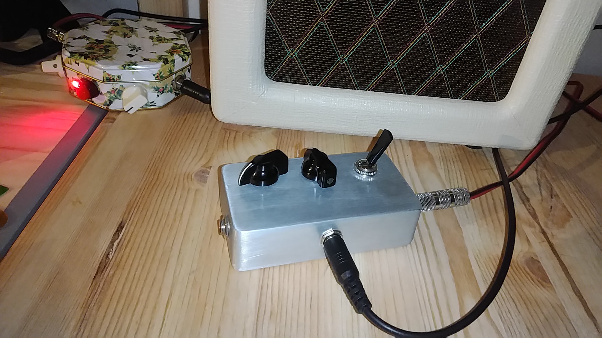
I built myself a resistive dummy load and an impedance simulator circuit because I like to crank up my little Class A into power tube saturation at 3 am. So I just take a lineout from the load box into the impedance circuit, then into a tiny solid state power amp, then back into the original guitar speaker. Does it sound like the amp cranked, just quieter? I don’t know, I’ve never turned the amp up past 1 without a dummy load. But it raises the hair on the back of my neck and I like it very much. It makes me orders of magnitude happier than the Amplug or V-amp I use when traveling. Plus, if I get signed, I can replace the tiny power amp with a giant one and a wall of cabinets and go play Edinburgh without changing my setup. (I guess I’d need to start a band or something, too.)
This was probably completely OT and a total thread hijack. Feel free to delete it. Sometimes I don’t know when to shut up. Plus this is all massively oversimplified, so to anyone out there who knows what they’re talking about and is enraged right now, so sorry.
Edit: I just reread the OP, and I guess this is actually on point. My message is this, @PickingApprentice. This is definitely doable in analog. If you want to use headphones instead of a cabinet, you’ll also need a cabinet simulator. If you’re ok with playing cranked yet quietly through a guitar cab, you can skip the cabsim. If you are a DIY kinda guy with some electronics experience, you can build this yourself for less than $100 (load box, impedance sim, cab sim, solid-state amplifier, I’m happy to share my designs). If you can find an off-the-shelf solution for this (somebody must have done it by now), I’d expect it to be in the $1k-$2k range.
Yep! Or right-side up depending on which way you throw the slider in Logic’s “Match EQ”. Not as peaky and closer to 100hz, which is probably the interaction of the mic / cab, but yes.
Great post. The blog article I’ve linked to above includes pretty much the exact frequency curve you’ve linked to here with the speaker impedance overlayed on the frequency response. I think we’ve all spent a lot of time looking at these. This one was the difference between white noise and the same noise fed through the cabinet / sm57 recording chain:
The only thing I’d add to your excellent overview is that I personally find what bad attentuators do to the sound to be way more noticeable than the loss of a little sparkle. Yes the speaker rolls off in the vicinity of 5k but the amp is putting out so much in that region that even if it’s at -20db or something, like it is in the Match EQ plot, it’s still super audible to me and an important part of the treble response of the amp and the weird phase cancellations inside the cabinet. When the attenuator shows up and that part of the curve is now gone, the only way to really get it back accurately is to use something like Match EQ. Again, something like the “deep / flat” and “bright / mellow” switches on the Palmer don’t really do it and were either just educated guesses or averaged approximations. I don’t know how the unit was designed.
From what I understand, Palmer only models the cabinet response and not the impedance response. Apparently deep vs. flat is supposed to represent open back combo vs. closed back 4x12. Some units have adjustments for British vs. American and the suchlike. I’ve never tried one.
I imagine the impact of the impedance response is both equipment-dependent (because the impedance effects are strongest at the edges of the cabinet responses, and those vary from model to model) and volume-dependent (because the impedance curves broadly mimic the Fletcher-Munson curves). My goal was good tone at low volume, so that’s how I did my AB testing, but there are lots of applications that I haven’t tested, so my observations may be skewed.
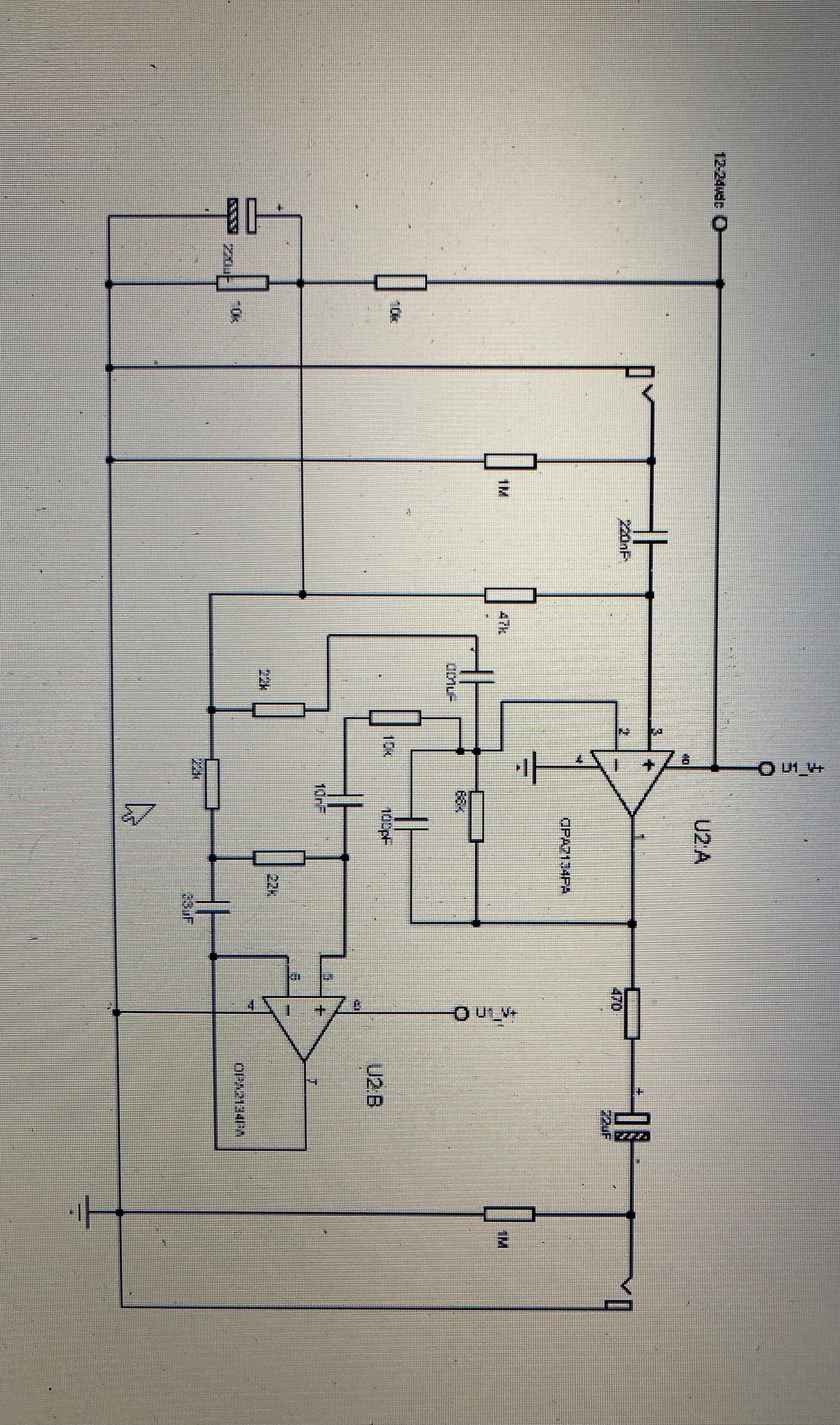
In any case, the reasonable options for non-digital use are either a reactive dummy load or resistive load plus impedance simulator EQ. The latter is easier and cheaper to DIY (inductors are a bitch), so I do that. I adapted the circuit from a Marshall patent I found on the internet. I found a few others out there as well. I’ve read that most solid-state amps include something similar, even the fairly cheap ones.
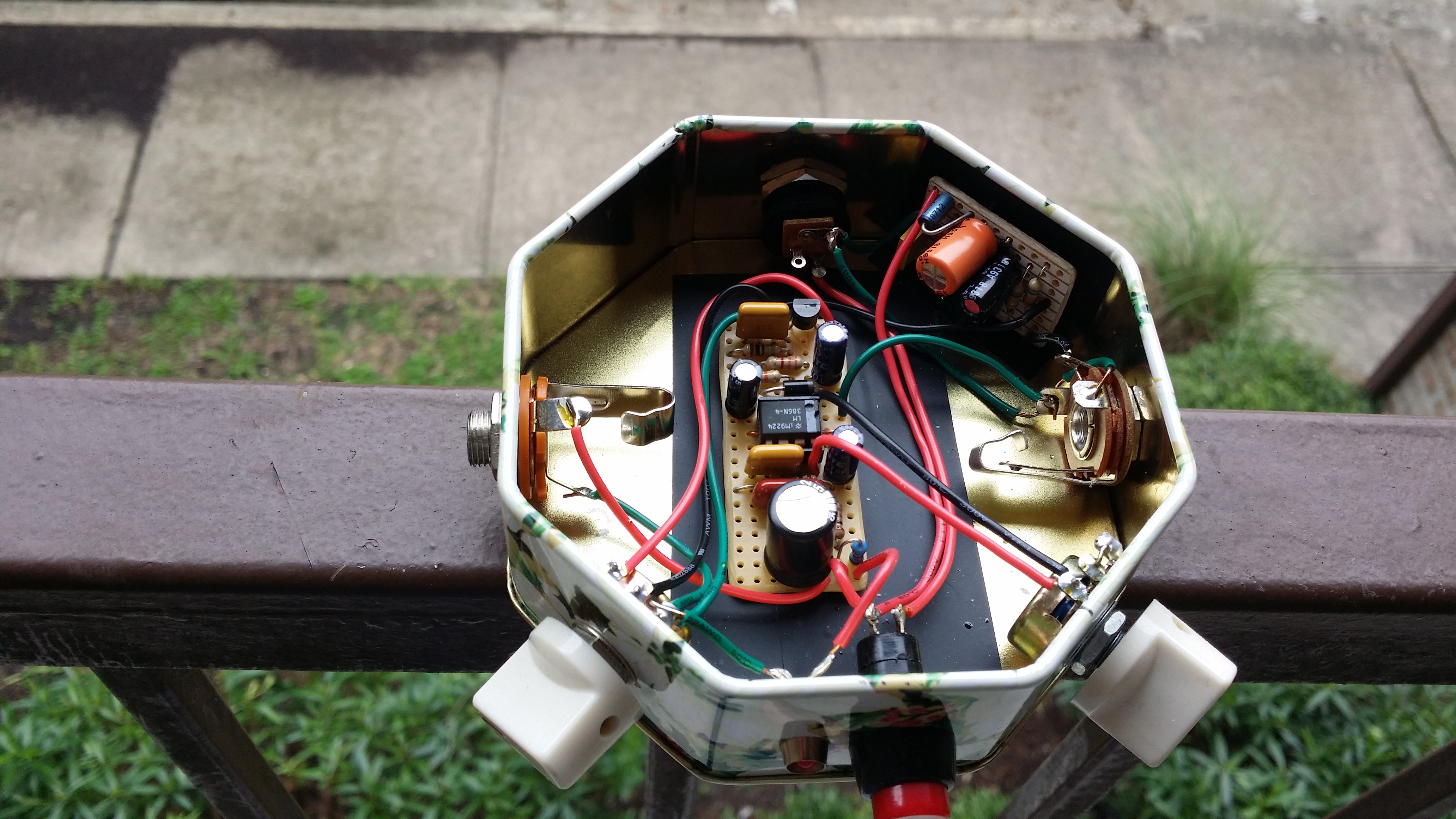
This is my slave amp. The impedance simulator (aka ‘reactance emulator’ for the google-minded) is the little daughter board at the top right. It’s about the size of a postage stamp. The other board is the amplifier itself.
So this is just a tiny amp that accepts the loaded-down output of your regular amp? What’s doing the loading, another box with a giant resistor in it, feeding this one? What do you plug this into, your usual cabinet?
So you’re dialing in the EQ compensation curve with the little “simulator” circuit, and that’s giving you your bottom and treble back?
If the primary amp has a speaker cabinet, you can use it. Or you can use any other cabinet you want, as long as it works with your slave amp. I use the cabinet from a retired modeling amp. If you want to use a PA or computer speakers or something, you’d put a cabsim after the impedance EQ and take the output from that.
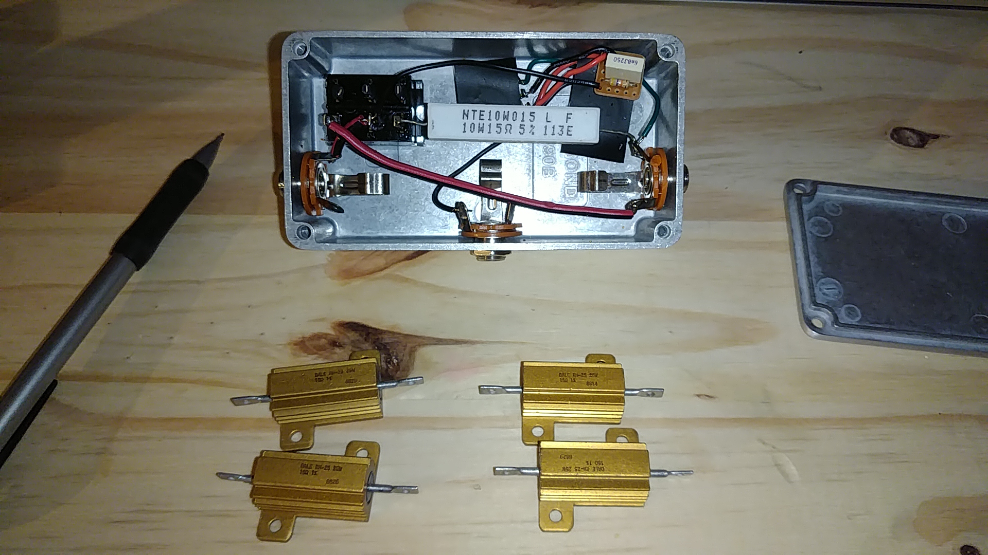
The switch is for dummy load vs bypass to an external cabinet. The line out works in both configurations. It has a volume and a tone control. I built it a few years before I built the impedance simulator, so I wanted to add some brightness back. Now I’d leave the tone control out. I always have it set flat.
The resistor should have a power rating at least twice the rated output power of the primary amp. The primary amp is a 4 watt Vox, and I like to run it around 4 on the dial, so a 10W ceramic resistor is plenty. It’s pressed against the bottom lid for heat-sinking purposes, but it doesn’t get too hot. For a 50W primary amp, you’d want at least a 100W resistor, or four 25W ones, like the ones in the foreground. This wouldn’t necessarily require a much larger enclosure, but it would have to be heat-sinked better.
You can use the primary amplifier’s rated output impedance as a guide for the resistor value, but it’s not super crucial. Bigger will be brighter, but stay within reason. DC loads don’t resonate, so this is actually easier on the primary amp than a reactive load or cabinet, then again running your amp at 10 is harder on it than running it at 1, so moderation in all things. And watch that the resistor doesn’t overheat if you crank it up.
You probably want the slave amp to be as clean and neutral as possible, but experimenting is best. You can use a 100W Class D car stereo amplifier to push a stack of cabinets with a Fender Champ, or tame your HiWatt so you can play it in the nursery. The general idea is the same, just the size of the slave amp and the size of the power resistor vary.
My primary amp doesn’t have reverb, but you can think of the line out of the dummy load as an effects send, and I put EQ, reverb, tremolo, etc. after all the distortion. I’m essentially using my amp as a pedal.
This is all just a variation on the Garnet Herzog, in case you’d like to do some short reading. It involves ‘American Woman’, so that’s kind of fun.
This thread makes very clear what I’ve been looking into - on and off - for about a year, thanks!
I would be very interested in the designs, if the offer is still standing. Could you share?
My setup story, so as to contribute some to this forum:
Currently I’m happy with my sound, but being (a bit too) busy: looking into shortening my unpacking/startup and tidying/shutdown times for daily use.
1/ I’ve started with saving the cable unpacking/packing. For this I’ve tried several compact wireless systems and settled on one. Check.
2/ Next step was getting a nice tone with a clean amp, i.e. through effects, in which I kinda succeeded, at least to my taste. Again, for daily (practice) use. For this I’ve developed my own effect pedal (original amp-ish gain stage, kinda original tone stage). Check.
3/ Final step is eliminating the amp+cab through a good cab sim, hooked up to the living room stereo. In comes this thread! Good information here. Wishing to cut down on development time, I pose my question.
*/ I am a bit comprehensive as to eliminating the amp from my chain… so if the tone without it is very not good: it will be back in the chain and the loading down is required, as I at least want to cut the cab from the chain.
First thing: cabinet simulator. This one is non-commercial and highly adjustable. I have a vero layout for it, if you’re interested and you don’t mind SMD. There are lots of other designs available. Let me know if you want some alternative schematics.
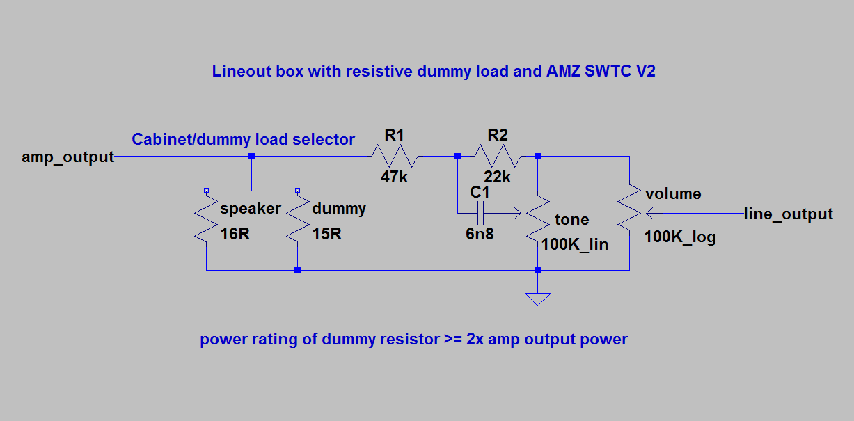
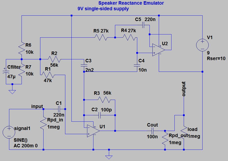
Next thing: If you decide to build a resistive dummy load, here’s the schem I used.
If you don’t need the tone control you can replace R1 and R2 with jumpers, and remove C1 and the tone pot. Just run the input directly to the line output and add the switch to select the speaker or the dummy load in parallel. If the max volume is too loud, add R1 back, and adjust the value to taste. The dummy resistor has to be 2x the amp’s output power, and the switch should be rated for reasonably high current so it doesn’t burn out. Exact value depends on your amp and how loud you play, but if the master amp is small, an amp or two is probably good enough.
In it’s simplest form, a resistive dummy load is just a resistor with an input jack, and a line out is just a voltage divider in parallel with the speaker or dummy load. The switch is just so you can keep the speaker plugged in and switch back and forth easily, rather than unplugging the dummy load and re-plugging the speaker. The switch selects between the speaker and the dummy resistor, but doesn’t affect the line out, which is always active. So you’ll have an input jack fed from the power amp, one output jack for line level, and another for speaker level. Just make sure you have a speaker plugged in when it’s not in dummy mode. Also, this circuit is completely passive, so no battery or adapter needed.
This goes after the dummy load and before the speaker sim, which feeds the slave amp (or stereo). I built mine into my slave amp, but you can put it in a separate box if you want. Or you can build it into the dummy load box before the line out. If you do that, you might want to make it switchable since there are some situations where you want both the speaker and the line out at the same time, and you only want the reactance emulator switched on in dummy mode.
Once I added the reactance emulator to my setup, I didn’t need the tone control on the dummy box anymore, which is why I suggest above that you might want to skip that part.
There are lots of possible ways to fit this stuff together, but if your slave amp is a home stereo, I would generally go either pedal → cab sim → stereo for a no-master-amp situation, or master amp → dummy box → reactance emulator → cab sim → stereo for a master-amp situation. Alternatively, if your slave amp has a guitar speaker in it, you don’t need the cab sim.
Like I said, there are lots of variations, so if you need any help or advice just let me know.
Thanks!
So, I fell into the cabinet simulator rabbit hole over the weekend… diverged quickly, but converged somewhat in the end. Final decision to be made about the cab sim, but here’s my story, while it’s still fresh.
First, my signal chain of choice will be:
Guitar → wireless → FX pedals → CabSim → Stereo system
For this, the CabSim needs a 1/4" jack input (instrument level) and 1/8" jack output (line level, dual mono). For reasons, it’ll also get a 1/4" jack output (instrument level).
Then the cab sim. A nice&quick DIY solution would be the MultiCab (your link) or RoG Condor (modded). However, comparing EQ curves all seem lacking in some respect. Also still need to account for line level output (gain 6-12 dB, output Z 100-600 Ohm). So I think I’ll end up developing my own circuit.
Ye old tale of the cab response quest, completely FYI (For You to Ignore).
So, Noob as I am, I went on the internet to find curves and comments on speakers and cabinets. Quickly felt like a farmer in a city, but believe I have a few handles: EQ, break-up, mic position, magic.
Magic. Because there a qualities to the sound, that currently do not have quantities, like “clarity” or “it sounds sterile”. Ignoring this aspect for my circuit.
Break-up. Yes, driving speakers too hard causes break-up, but this is not the kind of overdriven or distorted sound I’m seeking. Ignoring this aspect, at least initially.
EQ. Well, lots to find here. Speaker EQ is not the same as speaker in a (specific) cabinet EQ, so had to watch out for misreading some curves to be the one or the other. Looked at measured responses, but also several cab sim responses. Generally, a cab filters below 80-150 Hz and above 3-5 kHz. A 1x cab can look flattish, maybe a slight drop of 0-3 dB below 500 Hz, but no real peak. Going to 4x cab the curve gets lifted below 500 Hz rising ~6 dB to a 80-100 Hz peak. Ignoring al the wiggles, even a 1300-1800 Hz sharp dip of a few dB they all seem to have. Then a lot drop off somewhere in the 3-5 kHz region, but not before peaking with 8-12 dB (relative to the 500 Hz level). Sometimes exhibiting a bump or flat region 20-30 dB down at 7-12 kHz before dropping further, ignoring this also. Focussing on 4x12, ideally with some control for going from 4x12 to 1x12.
Mic position / angle. Forget every trend you think you saw for EQ. Re-positioning the mic, center cone, side, 1cm, 1 meter, 0 degrees, 45 degrees… results in drastical recorded sound (or EQ). Going from 0 degrees center cone to 45 degrees angle at center cone made one curve start dropping from 200 Hz going up, completely caving in from 1 kHz and up. So I think this should be a control worth adding to a cab sim.
Ye old tale of the cab sim quest, completely FYI (For You to Ignore).
So, Noob as I am, I went on the internet to find curves and comments and schematics on cabinet simulators. Found interesting comparison sites of Frank Nitsch and HexeFX, an Axe FX II document with cab sim curves on docplayer and a few DIY friendly sims. Interestingly, a lot dip at 250-500 Hz in stead of the measured dips at 500-600 Hz, but that could be due to my maybe limited findings or understanding.
Daniel Schwartz MultiCab, as per your link. 4x12" sim, BJT for break-up, but I don’t quite understand the abundance of control in the lower registers in comparison to the limited control in the upper region.
RunOffGroove Condor. 4x10" sim (with mods Marshall 4x12), no control, JFET for break-up. Looking at other schematics, I don’t see the point of 5 stages.
Valve Wizard cab sim. 4x12" sim, diodes limiting input signal, “cabinet” control first drops the bass peak, rotating further destroys treble peak (akin to mic angle). Headphone output only, though.
Tube Amp Doctor F.A.N.T.A. Reactive dummy load and cab sim. Found no schematic. Highly regarded by some. EQ looks like 45 degrees mic; dropping curve without treble peak.
Tech21 (SansAmp) Blonde (Joyo, Caline, Mosky clones available). Technically an amp sim, but “voice” pot controls mixing in a cab sim.
Also worth mentioning: Marshall amp sim circuit, Red Box mkII, Boss TM-3, Baja Reactor, AMT Guitar Cabinet Simulator, DeadAstronaut Astro-Sim, Radial Engineering JDX Direct-Drive.
Soooooo past time for an update.
After being delayed by holiday, extreme lead times on some parts, other projects and surviving covid… I developed and finally build my cab sim with line level output
Sound is good! To my ears at least. Have one issue yet to resolve…
The control “mic angle” controls the 3.4 kHz peak level, the “size” knob the 100 Hz bass boost. It has a “bright” switch, moving the peak from 3.4 kHz to 4-ish kHz and making it higher Q (more sharp), but it turned out to be very not nice so not using that… also I like it the way it is, so I’m currently not “fixing” this. It also has a “dip” switch, effecting a -10 dB dip at about 500 Hz.
Home stereo setup and aesthetics called for a non-stompbox-box.
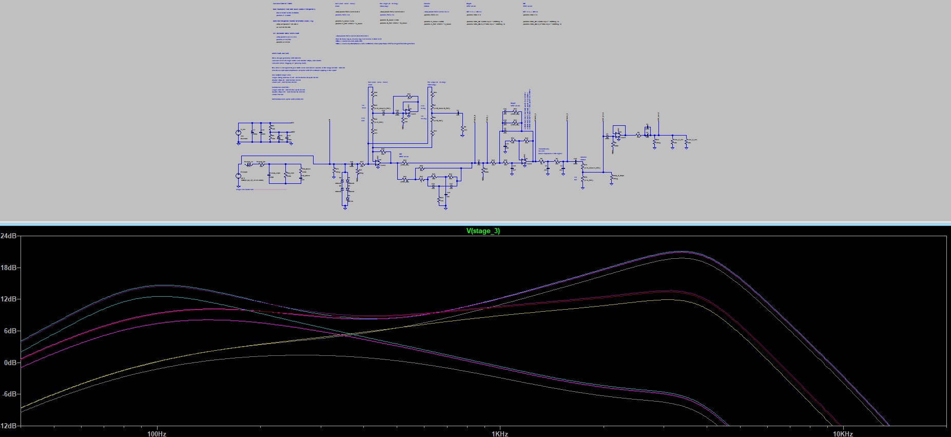
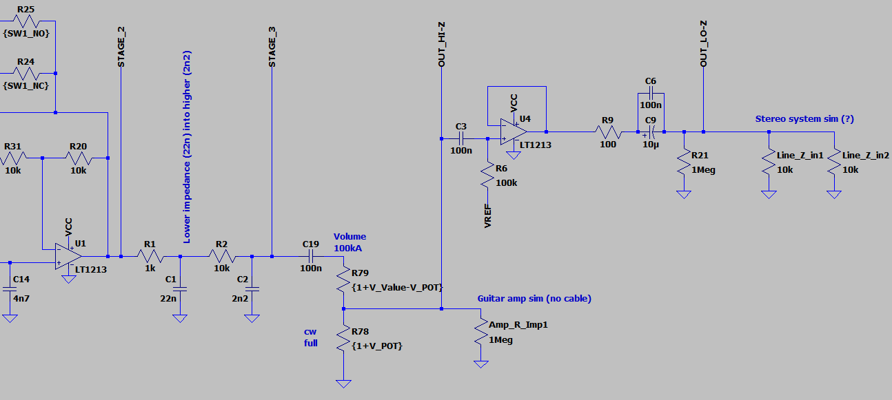
The circuit is no rocket science. First stage is borrowed from any old EQ pedal for “size” and “mic angle” controls. Then the optional “dip”, followed by a 1st order high pass, both passive. Then an active 2nd order low pass filter, aka Sallen-Key low pass*. Two 1st order low pass filters (taking impedance cascading into account) to achieve a total 4th order low pass filter. Passive volume, then a buffer for low impedance line level output.
*) For me this was the first time I tried this filter topology. After building the cab sim, it only “whistled” out of my speakers. Bypassed the op amps first to find the source, which turned out to be this S-K stage. Googled a lot and found the S-K could be used as an oscillator, because it having the tendency to ring around it’s resonance frequency. So of course, I got it to oscillate… LTSpice didn’t think it would, but it definitely did. So, whipped out a bread board, broke out of the pcb, rebuild the stage and started tweaking, using excel as my calculator. Learned stuff.
**) Also another minor issue when using 9V pedal power: op amp clipping. Saw this coming, as it’s going 20 dB up. But I’m using 24V supply. I prepared the pcb to accept dual/rail supply, just in case, later, maybe.
However, one issue is bugging me. Plugging it into my power amp, I have to really turn it up… I’m getting too low output out of it. No issue with my practice guitar amp, getting a good boost in level there.
My power amp accepts RCA and jack input at the same time, allowing for playing them together, i.e. mixing. Actually doing this, so I can play over songs maybe, the levels are low. Unplugging the cab sim mid-song, the song goes a lot louder instantly. So I’m guessing impedance issues at this point.
…writing this down, I realize I didn’t check if unplugging the RCA results in the same boost in the cab sim level.
However, I’m also missing volume level when plugging into the television’s sound bar. Not sure if this counts, since I also get half a second lag from this thing; may be some “smart” stuff going on there.
Then again, also my first time creating a dual mono signal… basically connecting left and right outputs, tip and ring at the output. Not sure about this.
→ I’m working on this. In the meantime, suggestions are very welcome.
@induction generally this is a great write up, however there are some finer details that might be worth going over, and quite honestly for whoever reads this if anyone, I’m not going to go into boring detail about the hows and whys etc.
The biggest thing with an impedance emulator really is narrowing down the condition that you wish to emulate include the resonant properties of the cab you wish to emulate, and depending on the amp, it’s design, the cab and the condition it is used, this may change drastically.
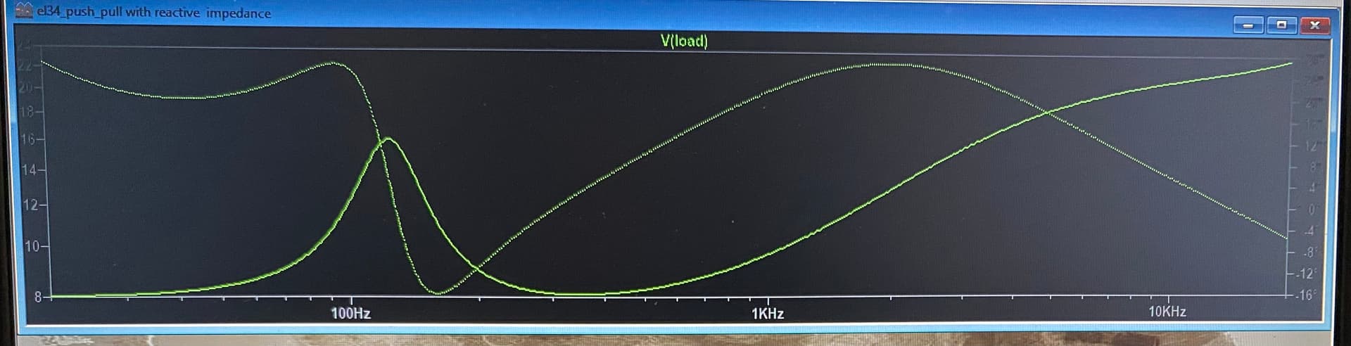
For example a 50W EL34 amplifier with an OT reflecting back 3.4K when attached to an 8r greenback cab, and the presence control up 1/3 or the way (about “4”) may look closer to this, especially if its -fb loop is still intact.
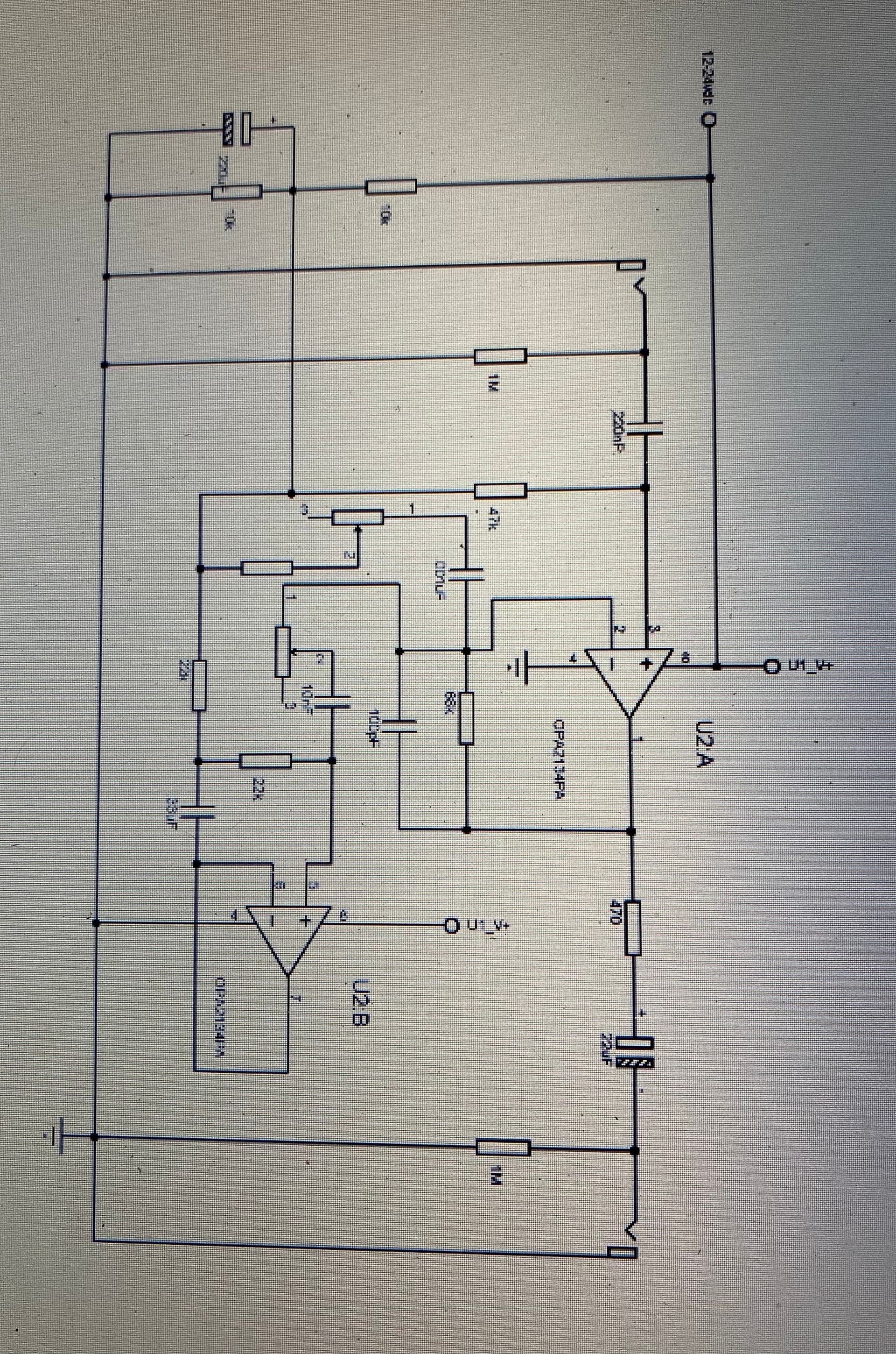
If you wanted to make it adjustable to sort of emulate an amplifier that has controls that remove -feedback on both ends (presence and resonance/depth) you could just add the following:
You can even expand this further, but at some point you run into the realization that a reactive load box becomes the simplest and best solution from a function, time, and cost perspective.

 )
)